Strain and Vibration Measurement Workshop

- Does extension wire resistance desensitize your strain gage measurement?
- If you correct for desensitization, does it change during
your test? - Is the 3-wire connection less susceptible to desensitization than the 2-wire connection?
- What if you use slip rings and the resistance changes?
- Is your strain gage measurement susceptible to high frequency electrostatic noise pickup?
- Is your measurement susceptible to low frequency (60 Hz) noise pickup?
- Is your static data really static data or is it zero shift?
- What is the best circuit for making static strain measurements?
- What if you want both static and dynamic data from one strain gage?
- The cable to your sensor is 300 feet long; can you make 20 kHz dynamic strain measurements with 1% accuracy?
- What is the best circuit for handling apparent strain affects on high temp static measurements?
Course Description
This workshop explores strain and bridge measurements in the “real world”. Unlike classroom lectures of pristine and perfect strain measurements, this workshop uncovers the measurement “gotch-yas” that are lurking in our actual test environment. This is a hands-on interactive workshop where actual sensor measurements are intentionally corrupted with a wide range of error sources; electrostatic noise, electromagnetic noise, long cables, high temperatures and others. The effect of these noise sources is discussed and understood, and then solved using various sensor, cabling and signal conditioner techniques.
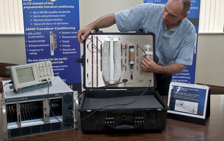
Alan Szary demonstrating various noise sources when measuring strain gages.
Gage factor desensitization
Some strain measurement circuits have measurement sensitivity, which is a function of lead wire resistance. While a “nominal” correction can be made at some reference temperature, resistance change during a test caused by temperature changes results in measurement uncertainty. Which circuits exhibit gage factor desensitization and which do not?
Susceptibility to noise coupling
Electromagnetic and electrostatic noise act on our wiring circuit at all times. Some strain measurement circuits are more susceptible to noise pickup than others. Several noise abatement techniques are available depending on the nature of the problem. This course will discuss:
- Noise abatement by filtering
- Noise abatement by shielding
- Noise abatement by twisting wires (magnetic)
- Noise abatement using CMRR (need for balanced circuits)
Zero shift
Some static strain circuits are very sensitive to the resistance match of the extension wires. Even a slight mismatch could lead to significant zero shift as the test article heats up and cools down. This course explores which measurement techniques are sensitive to zero shift and which are not.
Comparison of 2-wire dynamic strain measurement circuits
Dynamic strain measurements can use AC coupled instrumentation which eliminates concern for DC and zero shift performance. Since there is no need for DC performance, a minimal (2-wire) connection can be used. Since data exists at high frequency, channel bandwidth is often high and filtering CANNOT be used to eliminate noise. There are several techniques for measuring dynamic strain, this course will compare the noise immunity and accuracy characteristic of the following commonly used techniques:
- 2-Wire Wheatstone Bridge
- Single-ended Constant Current
- Balanced Constant Current™
Comparison of moderate temperature (<600 degF) static strain measurement circuits
At temperatures below 600 degF self-temperature compensated strain gages are often used. These gages are self-compensated to minimize zero shift caused by apparent strain as the base metal experiences thermal expansion. Since the self-compensated gage is a single gage element, it is often connected in a quarter bridge 3-wire configuration. This course examines the 3-wire Wheatstone Bridge configuration and compares it to a 4-wire constant current (Kelvin) technique.
Comparison of high temperature (>600 degF) static strain measurement circuits
At temperatures above 600 degF it is more difficult to self-temperature compensate a single gage. At these temperatures it is common to use a pair of high temperature (uncompensated ) strain gages configured as a half bridge. Often one gage will be the sensing gage, and the other will be a compensating or dummy gage. Traditionally the Wheatstone bridge half bridge circuit is used for these measurements. This course will explore the pitfalls of the half bridge circuit and propose alternative methods. The following circuits will be explored:
- 3-wire Wheatstone bridge
- 5-wire Wheatstone bridge
- 3-wire Constant Current
- 5-wire Constant Current
Effects of long cables
All sensors interact with the cable capacitance to create a new boundary condition. Often the input cabling boundary condition is ignored when designing the high frequency transfer function of the measurement system, sometimes with devastating effects! This course will discuss:
- Calculating cable roll-off caused by cable capacitance (first order approximation)
- Measuring cable roll-off in-situ
- Automated means of measuring cable roll-off from the instrumentation room (sensor stim.)
Half bridge measurements
Whether used with two active arms or one active and one compensating arm, the Wheatstone ½ bridge can be used to solve many difficult strain measurement problems. Unfortunately, when used with long wires in a noisy environment the remote half bridge is extremely susceptible to noise pickup, which restricts it’s use to only heavily filtered static type measurements, This courses examines various half bridge topologies and introduces one half bridge topology that is immune from noise pickup allowing for both static and noise free dynamic measurements from the half bridge.
Verification/validation techniques
It is good practice to have an end-to-end checkout of the entire measurement system just prior to a test. A good methodology would confirm sensor and cable health, excitation, and gain frequency response of the signal conditioner. To make this a viable methodology, the end-to-end test should be easy, quick, and be performed from the instrumentation room at the push of a button. The resistive strain gage has unique characteristics that make it an ideal sensor type for end-to-end pre-test checkout. This course will explore sensor and cable health test methods, and a technique for stimulating the strain gage to generate its own “sensor-based test signal”.
For more information about this training contact:
Phone: 607-277-3550
E-Mail: sales@pfinc.com